The global steel industry is intensifying its efforts to move away from fossil fuels in order to reduce its specific CO2 footprint. Utilizing electricity to melt and blend metallic ferroalloys such as scrap steel, pig iron, direct reduced iron (DRI), and hot-pressed iron (HBI) helps reduce the CO2 footprint, but it also presents new challenges. Over the past few decades, various electric arc furnace (EAF) designs and process variations have been validated and have contributed to the development of future EAFs with higher DRI and HBI inputs to meet steel quality requirements.
In response to climate change, many regions around the world have chosen to first limit CO2 emissions into the atmosphere, or even demand zero CO2 emissions. Since the steel industry is a significant part of this, strategies for gradually reducing CO2 emissions have been developed to align with local government frameworks and societal interests.
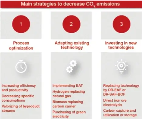
Figure 1 shows three main strategies available to each steel manufacturer. First and foremost is process optimization (1), which is a process that requires direct action and some capital, but not large investments. It directly reduces CO2 emissions per metric ton of steel by increasing output and/or optimizing material utilization. Therefore, external experts can help determine the fastest path to the optimal production strategy. The impact of this strategy is very effective, but also limited. In fact, scrap-based electric arc furnace (EAF) operations can reduce CO2 emissions to below 100 kg per metric ton of steel by reducing power-on time (PON), power consumption per ton of steel (kWh/t), or optimizing the use of different carbon addition methods (carbon blocks in baskets, carbon injection, etc.). To go beyond the limitations of process optimization, investment is first required to adapt to existing technologies (2). Further reductions in CO2 emissions can be achieved by replacing outdated systems with more efficient machines and by switching to low-carbon (e.g., natural gas), carbon-free (e.g., hydrogen or ammonia), or non-fossil fuels. This approach typically requires more investment and sometimes even research activities. Finally, carbon direct avoidance (CDA) in its final stage means investment in new technologies (3) and results in significant investments of billions of dollars or euros. While the first and second steps are best suited for electric arc furnace-based steelmakers, integrated steel mills cannot avoid the third step in order to achieve zero emissions.
When an integrated steel plant chooses to undertake the third step, numerous challenges arise, requiring a shift from oxygen-based steelmaking to electric arc furnace (BOF) steelmaking while maintaining the same secondary metallurgical refining processes and equipment. Beyond the extensive project management required, the operation and maintenance of an EAF differ significantly from that of a conventional converter (BOF), as detailed in Reference 1. This impact encompasses a wide range of issues, from metallurgical problems with significant implications for secondary metallurgy (e.g., ferrous feedstock, impurities, and residual elements), to new slag design and recycling, flue gas treatment considerations, new and various safety risks, and maintenance issues that severely affect EAF steelmaking productivity. The production and performance of a 300-ton EAF differ from that of a 300-ton BOF converter, and most of the data discussed are theoretical in nature, as actual industrial data are difficult to obtain.
Once the decision is made to use an electric arc furnace (EAF) for steel production, a suitable furnace type must be selected to meet the requirements of high capacity and low consumption, ultimately achieving low cost and low CO2 emissions. The following sections will introduce several EAF designs to provide a broad understanding of the capabilities and potential of EAF technology. For applications such as processing large quantities of metallic iron pellets from iron ore, some of these options are theoretical exercises, with entire sectors and educated groups speculating on how EAFs can replace high-performance, high-quality production equipment like BOFs. To enhance the value of the discussion, this paper presents actual production data for different types of EAFs to theoretically illustrate the less-than-optimistic prospects of EAF design.
Different types of electric furnaces and their emissions
Electric arc furnaces (EAFs), especially when using direct reduced iron (DRI), are expected to play a significant role in future steelmaking. Various EAF technologies have been developed and are available on the market; three main design schemes are shown in Figure 2. Of course, many more design options have been developed in the past; therefore, this list is not exhaustive.
Non-preheated metal charge: Conventional electric arc furnaces: multi-basket, single-basket, double-shell, Con Arc; Preheated metal charge: Conventional basket preheating, Dan Arc, vertical shaft furnace, Quantum electric furnace, Sharc, Eccoarc, Coss, EPC, Ecoshaft, Constar electric furnace, ECS; Continuous charging in electric furnaces: hot and cold DRI, molten iron.
Most of these are traditional scrap-based EAFs, top-loading via a basket without any additional preheating technology. Of course, there are many different EAF designs in this category, supporting feeding with one or more baskets and powered by either AC or DC. If the two furnace shells are very close to each other (double-shell EAF), a single set of electrodes can be used to melt the scrap in both shells separately. This design allows for alternating power supply to two independent EAF furnaces; however, the increased productivity benefits may be offset to some extent by energy losses within the furnace.
Several concepts exist on the market that utilize the energy contained in the flue gas. The earliest and most direct preheating method is to directly feed the flue gas into the scrap basket (traditional scrap preheating). This method has several difficulties, such as thermal deformation of the scrap basket, basket logistics issues, and the formation of unpleasant odors inside and around the electric arc furnace workshop. Therefore, different technological solutions have been developed. The most common method currently is horizontal preheating of scrap steel. A slow-in, fast-return conveyor continuously feeds scrap steel into the EAF (Electric Furnace Air Facility) from an opening opposite the transformer. After tapping, approximately 40% of the steel remains in the furnace, while the high-temperature flue gas flows in the opposite direction to the scrap steel’s movement on the conveyor. Tenova pioneered the Consteel scrap preheating system in the US, and this technology is offered by several original equipment manufacturers (OEMs).
An effective preheating method is vertical shaft furnace preheating of scrap steel, as the flue gas flows upwards through the scrap shaft. Many vertical shaft furnace variants have been built over the years; the latest versions use a water-cooled finger system to ensure preheating of the entire scrap column. These furnaces still use basket batching, just like traditional EAFs. However, because scrap preheating lowers the flue gas temperature, additional flue gas treatment is required.
Additionally, if it is necessary to guarantee specific quality, traditional EAFs can also be operated using DRI (Dry Intake), HBI (High-Intensity Bismuth), pig iron, or molten iron from a blast furnace. These electric arc furnaces require continuous feeding via the furnace cover (DRI/HBI) or the upper furnace shell side wall, furnace door, or eccentric bottom tapping (EBT).
Based on actual industrial results, three main electric arc furnace designs were compared by selecting the most developed and mature concepts and installation numbers. Regarding decarburization, the following data were reviewed:
Carbon dioxide emissions range 1 and 2.
Electricity consumption.
Annual performance data from steel mills with appropriate steel output (80 tons) and high performance levels (low outages/high uptime) were selected from a global best-practice database (benchmark) for evaluation. For simplicity and comparability, it was assumed that the material composition of all carbon carriers in all steel mills was identical to calculate emissions for Scope 1. Similarly, for Scope 2 calculations based on EAF power consumption, the same grid factor was used for all steel mills.
Figure 3 shows CO2 emissions for Scope 1 and Scope 2, along with the sum of the three different electric arc furnace (EAF) design technologies already explained: conventional EAF, scrap preheating EAF, and DRI-based pelletizing EAF. For the last group of DRI-based EAFs, only gas-based emission reduction operations were considered. Within each group, steel mills are sorted in ascending order of steel output weight (size). It is clear that EAF size has no impact on CO2 emission levels.
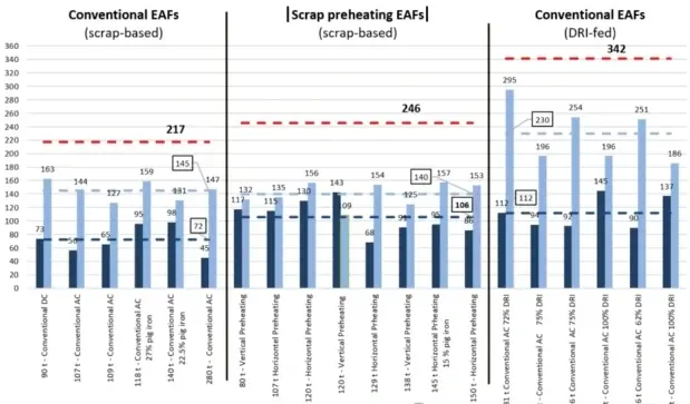
The minimum emission level in Scope 1 averages 72 kg CO2/t in conventional electric arc furnace groups, and up to 98 kg CO2/t in electric arc furnaces using pig iron as metallic iron. However, there is a minimum carbon requirement for operation, limiting further reductions of approximately 45 kg CO2/t.
The eight scrap preheating electric arc furnaces achieved an average of 106 kg CO2/t in Scope 1. The main reasons for this difference are the increased carbon injection during the flat melting process to maintain slag foaming, and the fuel consumption in the flue gas treatment (vertical furnace) – the horizontal preheater section uses activated carbon to treat dioxins.
The DRI carbon input (1.4% C in this example) results in a higher CO2 level (average 112 kg CO2/t). A certain amount of carbon is required in the DRI to reduce FeO. Any excess C can be used for FeO slag reduction and combustion via oxygen injection. The carbon in the DRI is a more efficient carbon source compared to carbon in the basket charge or injected carbon.
CO2 emissions for Range 2 are calculated using a grid factor of 0.376 kg CO2/kWh; logically, emissions are calculated based on the electricity consumption for each category.
Figure 4 shows the electricity consumption for three different EAF technology groups. Size was not a significant factor in the selection of these EAFs; the more important factor was the metal charge mixing ratio (scrap/pig iron/DRI/HBI/molten iron). The average electricity consumption of conventional EAFs in this database was 386 kWh/ton. A well-managed, efficient EAF could achieve an optimal value of 338 kWh/ton compared to conventional EAFs. The impact of poor pig iron melting performance was evident in the two steel mills using 22-27% pig iron. The overall effect of using a preheated scrap EAF was a reduction in electricity consumption to 373 kWh/t, with higher preheating efficiency in the vertical shaft furnace. The electricity consumption of the EAF using DRI was 506 kWh/t (average). The main factors affecting the required electrical energy consumption are the amount of DRI produced from the metallic iron raw material and the melting behavior of the DRI, which are closely related to the composition of the iron ore used to produce the DRI and the temperature at which the DRI is added to the electric furnace. Lower consumption values can only be achieved through thermal DRI (hDRI).
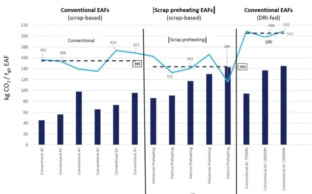
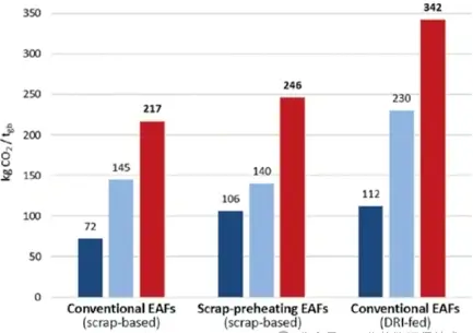
Figure 5 shows a summary and overall overview of CO2 emissions for three different EAF technologies. The total emissions are also the lowest, ranking lowest among conventional electric arc furnaces (range 1) and with a generally good average power consumption.
Optimized design of conventional AC electric arc furnace
To achieve optimal conventional AC electric arc furnace (EAF) performance, it is essential to ensure that the entire EAF design and control system comply with certain safety standards. [2,3] This requires a comprehensive strategy that combines high productivity with safe operation. To provide further information, some key components of modern state-of-the-art EAFs are briefly described. Today, the range of steel grades produced using EAFs extends from long products such as rebar to special bar quality (SBQ) to flat products such as electrical steel for transformers. The final steel product quality requirements dictate the ferrometallic feedstock needed for EAF smelting, which significantly impacts EAF design. Rebar producers may focus on balancing different scrap weights and corresponding costs with scrap quality. Slab producers need to focus on minimizing residual elements, using the highest possible proportion of raw materials from ore (e.g., DRI, HBI, pig iron, etc.) and the lowest possible residual element content. Generally, EAFs and their operation should be designed with as few baskets as possible – ideally, only one basket should be used per heat of steel. Since single-basket operation is extremely difficult and rare (except, for example, a vertical shaft furnace with an additional basket), modern conventional EAFs will strive to achieve double-basket charging operation. In this case, the basket and furnace volume need to be designed according to the type and volume of the metal material.
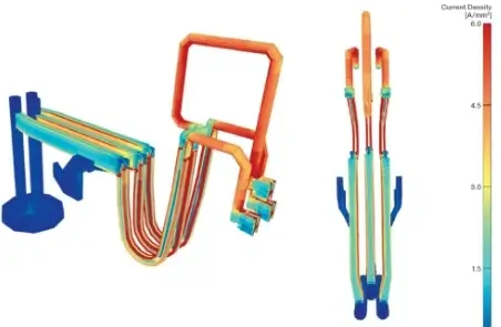
Under this premise, the design of the EAF high-current system (HCS), secondary short network, high-current water-cooled cable and conductive cross arm will effectively input electrical energy and reduce maintenance problems. A very important design tool is to use the finite network method (FNM) to simulate the entire system. Through FNM simulation, [4] the design was optimized to achieve the highest possible electrical energy input symmetry during EAF operation. One of the simulation parameters is the current density distribution from the transformer to the electrode tip in the system. The design results of the current density distribution are shown in Figure 6.
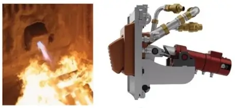
Furthermore, since chemical energy accounts for at least 30% of the current input energy of electric arc furnaces, the burner system used is another important component. As shown in Figure 7, the furnace wall oxygen burner can achieve a thermal power level of up to 6 MW. For the direct carbon-oxygen reaction in the molten pool, similar to oxygen blowing in a converter, in addition to burner mode, oxygen lances with an oxygen supply of up to 2200 Nm³/h can and should be selected. Depending on the scrap mixture and other factors, various operating profiles can be selected in state-of-the-art burner systems for automatic control and power input execution. The inclined arrangement of the oxygen lance burners provides an ideal angle, offering greater flexibility for oxygen blowing in the molten pool reaction and for heating and cutting scrap in burner mode. Furthermore, it helps to accommodate the different melting behaviors of scrap with varying densities.
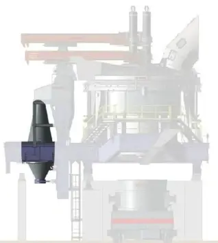
The design of the electrode cover drive frame structure of the electric arc furnace is another special and important aspect, requiring robustness, strength, rapid upward and rotational movement, and the ability to allow the electrodes to be pulled out and rotated independently without the furnace cover. Special attention should be paid to the support bearing system for optimal maintenance. Furthermore, due to its streamlined structure, the current frame design can significantly increase the size of the electric arc furnace. Figure 8 shows the main loads on this frame and bearing system in modern electric arc furnace designs.
For any new EAF, a key recommended technology is spray cooling for the furnace cover and fourth orifice (Figure 9). Pressureless cooling reduces maintenance requirements and is highly beneficial for the safe operating conditions of the components. The overall weight is reduced due to the elimination of a bulky cooling water piping system, and the hydraulic system experiences less pressure. Overall, this reduces the time required for operation. Furthermore, spray-cooled furnace covers are lighter than other options, allowing for faster rotation of the upper furnace shell system, which reduces power outages (POFFs) during basket charging and heat loss during furnace cover opening, directly impacting kWh/t metrics and production efficiency. However, special attention is needed regarding cooling water return. To ensure safe and reliable return water to the electric arc furnace top plate, a Venturi pump must be used to apply suction to the furnace cover return water collection ring. The advantages of this system in terms of operation and maintenance, along with the extremely long service life of the installed spray pump (completely maintenance-free), mean that the significant installation work required for the spray-cooled furnace cover return water suction can be quickly recouped.
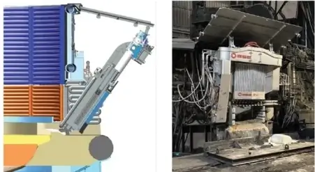
“Is the future all about unmanned operation?” This is a sentiment echoing in most U.S. steel mills. During electric arc furnace (EAF) operation, the area around the EAF becomes an inaccessible red zone, making automation systems more crucial than ever. Therefore, deploying automation systems is now more important than ever, with the latest recommendations focusing on keeping operators away from the furnace while utilizing automated taphole cleaning and replacement equipment, as well as automated, camera-controlled taphole filling and guide sand equipment, such as the Eccentric Hearth (EBT) taphole cleaning robot (THM) and guide sand filling robot. Another technology that may be included is an automated furnace door system, capable of safely cleaning the furnace door platform and passageway during operation and safely opening and closing the furnace door during EAF operation. Figure 10 shows a schematic diagram of the furnace door and includes an actual photograph from an EAF workshop in Turkey. These automation systems do indeed facilitate operational standardization, reducing operation time and leading to increased productivity, which is essential for narrowing the productivity gap between EAFs and converters, especially when using cold DRI or even HBI feed.
Finally, the electrode conditioning system must be fully considered. Systems like ELARC offer a highly dynamic, adaptive control concept that ensures optimal arc stability, reduced electrode consumption, and superior energy efficiency, even under challenging melting conditions. Recent tests have even shown that simple adjustments to parameter tuning and current setpoint tuning can not only increase power input (MW) but also reduce flicker.
The ratio of slag volume to CO2 in blast furnace pellets has been a subject of concern regarding whether DRI produced from blast furnace pellets can be added to electric arc furnaces or used as the sole source of metallic iron for electric arc furnace steelmaking. It is generally believed that excessive gangue content and low iron content in DRI produced from blast furnace pellets lead to excessive slag in the furnace, resulting in inefficient and uneconomical steelmaking processes. A direct comparison should provide some insights when studying this topic. Assuming that the chemical composition of both types of pellets is representative, [7,8] Table 1 (column titled “Raw Materials”) shows that DR pellets have a higher iron content and lower levels of all other oxides. Here, gangue refers to other unmentioned oxides. The carbon content of both types of pellets remains constant.
When simulating the direct reduction of these particles at temperatures below their melting point, the following chemical composition of DRI made from both types of particles is listed in the “DRI” (Reduced to DRI) column. It can be seen that the initial 2.2% gangue in DR pellets and 8.0% gangue in BF pellets become 3.1% and 11.2% respectively in DRI. For simplicity, it is assumed that the metallization rate is 100%, and iron oxide exists only in the form of hematite.
When designing steelmaking slag, metallurgical recommendations suggest balancing acidic/ampholy oxides (such as SiO2 and Al2O3) to the desired basicity. Which basicity is necessary to achieve which quality target is beyond the scope of this discussion. Table 2 shows the slag metallurgical considerations and their impact on yield and slag ratio. For an electric arc furnace using 100% DRI pellets, the total SiO2 and Al2O3 per metric tonne of pellets are 28.9 kg/t of feed and 110 kg/t of feed, respectively. When the B2 target (CaO/(SiO2+Al2O3)) is set at 2.2, the demand for pure CaO is 63.6 kg/t feed and 242 kg/t feed, respectively. Adding these together yields 92.5 kg slag/feed and 352 kg slag/feed, respectively. Since there is no metal yield from the inputs of SiO2 and Al2O3, and a potential 2% yield loss during the process, the final iron yields for the two DRIs are 95% and 87%, respectively. The slag ratios are 97.3 and 404.7 kg slag/t tap, respectively. Currently, a good electric arc furnace operation yields approximately 150 kg slag/t tap, making the DR pelleting situation very attractive, while the BF pelleting situation is inefficient – not to mention the increased volume required for the electric arc furnace and the added amount of slag that needs to be considered for transportation, processing, and sales.
Integrated steel producers are considering smelting furnace technology, learned from non-ferrous metal production, to significantly reduce CO2 emissions. The reason for choosing smelting furnaces over electric arc furnaces is the flexibility of using lower-grade iron ore, even fine powder instead of pellets, thus allowing for DRI (distilled iron refining) in fine powder form. Liquefaction in a smelting furnace is a continuous process, but tapping is done in batches. It needs to be carburized to 2.5-3.5% to obtain “synthetic hot iron.” In the subsequent converter process, oxygen blowing removes [C], providing chemical energy, which is the only energy source after latent heat. One of the main reasons for the infeasibility of high-slag-volume electric arc furnaces, calculated using Table 2, is the consideration of the large slag volume. Further considering and selecting the smelting furnace technology as the primary and initial reason—CO2 emissions—Table 3 shows the subsequent CO2 emissions for Scope 1 and Scope 2 compared to electric arc furnaces and two types of iron ore pellets. This review indicates that smelting furnace technology leads to higher CO2 emissions in order to reduce uneconomical slag volumes and proportions. The oxygen-blown converter remains necessary to remove dissolved carbon and emits 150 kg of CO2 per metric tonne per tap – similar to a scrap-based electric arc furnace (EAF). Therefore, the actual CO2 emissions of the entire DRI-smelting furnace-BOF process route are considerable, a conscious decision that every steel producer must make. Since the annual production capacity of smelting furnaces has not yet exceeded 1 million tonnes, but EAF is a mature technology with a tap weight exceeding 300 tonnes, this consideration may increase skepticism about smelting furnace technology and certainly reveal uncertainty surrounding this strategic decision.
Furthermore, the slag from the smelting furnace can be designed to resemble, or even be identical to, blast furnace slag. No special metallurgical work is performed here regarding dissolved elements in steel. Therefore, the basicity of “synthetic blast furnace slag” can be defined as around 0.9-1.3, giving it the potential to be used in the cement industry after crushing, just like today’s blast furnace slag. The role of FeO in this slag is not entirely clear. FeO, and possibly even iron oxide at a higher oxidation stage, originates from less than 100% DRI metallization. The reduction of FeO to Fe in the smelting furnace is suspected to be incomplete. Some original equipment manufacturers claim that all FeO, and even some SiO2, is reduced to [Si] from the synthetic hot iron from the smelting furnace. If this is not the case, the impact of FeO in synthetic blast furnace slag on cement utilization needs to be evaluated.
[Conclusion] Reducing CO2 emissions during steelmaking is a crucial strategic decision that will profoundly impact the business and profitability of steel producers. Correct technological decisions require in-depth analysis, until certain details are not overestimated. This paper compares different electric arc furnace (EAF) designs that may be a consideration for future profitable production in integrated and small plants, and their respective impacts on Category 1 and Category 2 CO2 emissions.
Different industrial solutions are proposed and compared. Among them, EAFs employing metal charge preheating devices are not highly efficient at reducing CO2. Conventional EAFs using scrap steel or pig iron as raw materials, with good operation and maintenance, have the lowest emissions and are the most cost-effective with the help of trained personnel and specialized knowledge. Some key details of conventional EAFs are highlighted and described. A brief comparison with alternative smelting furnace technologies reveals that smelting furnaces do indeed produce less slag, a clear advantage, but the disadvantage is a significant increase in CO2 emissions. Different solutions can be chosen depending on the strategic objectives of the steelmaking enterprise undergoing transformation. If the primary and overall objective should be minimal CO2 emissions, then conventional EAFs appear to be the most profitable option.