As the core equipment of steelmaking, the quality of converter lining construction directly determines the service life and production efficiency of converter. This plan combines advanced domestic and foreign experience to build a systematic solution from three dimensions: material selection, process optimization, and quality control. It focuses on the differences in working conditions in different parts and proposes a full-process technical system of “zoning material selection + precise construction + dynamic maintenance”.
1.Material system and performance adaptation
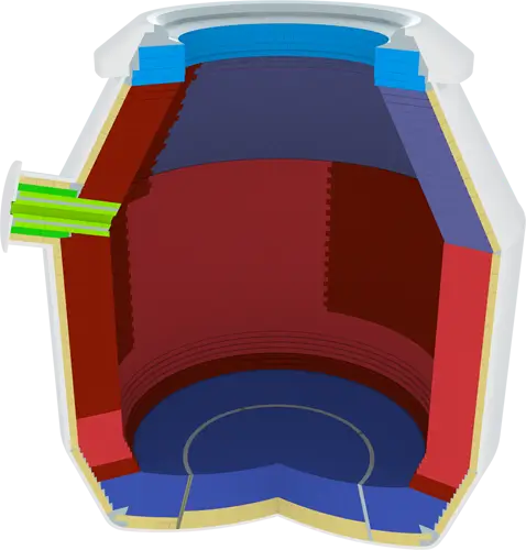
(1) Selection of working layer materials
Magnesium carbon brick system
Slag line area: MT18A magnesia carbon bricks (MgO ≥ 88%, C ≥ 14%) are used. The slag erosion resistance index is 35% higher than that of ordinary magnesia carbon bricks, which is suitable for areas with slag erosion rate > 2mm/furnace.
Charging side: Anti-oxidation magnesia carbon bricks with 0.5% metallic aluminum powder are used. The residual strength retention rate reaches 82% after 1600℃×3h thermal shock test.
Steel outlet: Equipped with integrally cast magnesia carbon casing bricks, the inner diameter tolerance is controlled within ±0.5mm, and filled with high-aluminum ramming material to ensure no leakage for more than 2000 thermal cycles.
Amorphous material application
The annular area of the furnace cap adopts Al₂O₃-MgO self-flowing castable material, with construction fluidity ≥220mm and volume density of 2.95g/cm³ after drying at 110℃×24h. The air-permeable bricks are filled with corundum quick-drying anti-seepage material, with a penetration depth of ≤1mm/24h, which effectively blocks the penetration channel of molten steel.
(2) Optimization of permanent layer materials
The fired magnesia bricks use fused magnesia aggregate (MgO ≥ 97%), with an apparent porosity of ≤ 16%. After firing at 1550℃ × 3h, the linear change rate is only -0.12%. A 5mm thick Helu ceramic fiber paper expansion joint is set between the permanent layer and the working layer, and the compensation coefficient is 0.8%/1000℃ to avoid thermal stress concentration.
2.Standardized construction process
(1) Construction preparation
Environmental control
A temperature and humidity monitoring system is set up in the masonry area. Construction can only be carried out when the ambient temperature is >5℃ and the relative humidity is <70%.
Refractory bricks need to be preheated at 200℃×24h, and the moisture content should be ≤0.3%.
Equipment calibration
Use a laser rangefinder to locate the center of the furnace, with an error of ≤±1mm.
The amplitude of the vibrating rod is controlled at 0.5±0.05mm, with a frequency of 12,000 times/min, to ensure that the density of the ramming material is ≥2.8g/cm³.
(2) Sectional masonry technology
Furnace bottom construction
The permanent layer is built by the “cross method”, with the upper and lower layers of magnesium bricks staggered at 90°, and the mortar joint thickness ≤1mm.
The laser centering system is used when installing the air-permeable bricks, with a positioning accuracy of ±0.2mm, and silicon carbide sealing material is filled around the tail pipe.
Furnace body construction
The working layer implements the “spiral rising method”, each ring door brick is displaced ≥ 3 pieces, and the expansion joints are arranged in “three horizontal and four vertical”, with the spacing controlled at 1.2-1.5m.
The ear shaft part adopts prestressed anchoring technology, opens a dovetail groove on the surface of the refractory brick, and implants 310S stainless steel anchors with a diameter of 8mm.
Furnace cap construction
Use an adjustable arc template to ensure that the roundness error of the cone part is ≤3mm/m.
The furnace mouth brick pressing material uses magnesium dry vibrating material, which is rammed in three layers, and the compaction coefficient of each layer is ≥0.95.
(3) Key Node Control
Transition zone treatment
Customized special-shaped bricks are used for the arc transition section between the molten pool and the furnace bottom, and the curvature radius deviation is ≤±2mm.
A 2mm thick phosphate binder is applied between the permanent layer and the working layer to form a transition bonding layer.
Baking furnace curve optimization
The “three-stage heating method” is adopted:
Low temperature section (room temperature -300℃): heating rate ≤15℃/h, constant temperature for 8h to remove free water;
Medium temperature section (300-800℃): heating rate ≤25℃/h, constant temperature for 12h to complete the decomposition of crystal water;
High temperature section (800-1200℃): heating rate ≤35℃/h, constant temperature for 24h to achieve sintering densification.
3.Quality Control System
Infrared thermal imaging detection
After each layer of masonry is completed, the surface temperature is scanned, and the area with temperature difference >15℃ needs local rework.
During the baking process, the furnace shell temperature is monitored in real time, and the emergency cooling system is activated when the local hot spot is >250℃.
Ultrasonic flaw detection
Spot check the key parts (air permeable bricks, steel outlet), and judge it as unqualified when the defect equivalent diameter >φ3mm.
(2) Acceptance criteria
Dimensional accuracy
Furnace verticality deviation ≤5mm/m, total height error ≤15mm.
Expansion joint width deviation ≤±1mm, straightness error ≤2mm/m.
Physical and chemical indicators
Working layer apparent porosity ≤18%, compressive strength ≥80MPa (1400℃×3h).
Permanent layer load softening temperature ≥1650℃ (0.2MPa).
4.Innovative technology applications
3D printed prefabricated parts
For complex structures (such as breathable brick bases), Al₂O₃-ZrO₂-C quality printed parts are used, with a dimensional accuracy of ±0.1mm and a 40% increase in installation efficiency.
Intelligent temperature control system
The embedded optical fiber sensor monitors the temperature gradient in real time and automatically adjusts the heating power when ΔT>50℃/h.
Nano-modification technology
Adding 0.3% nano-SiO₂ to the castable increases the thermal shock parameter (TSP) from 250 times to 400 times (1100℃ water cooling).
5.Converter drying solution
After putting firewood and coke into the converter, heat it up for 5 to 8 hours. When the temperature rises to 1200-1300℃, molten iron can be added for trial burning. When smelting the first batch of steel, all molten iron must be added, and scrap steel is not allowed.
6.Furnace type optimization
Based on CFD simulation, the thickness distribution of the furnace lining is adjusted to increase the thickness of the slag line area by 15% compared with the traditional design, and reduce the thickness of the trunnion area by 10%.
Through the collaborative innovation of materials, processes and maintenance, this solution extends the life of the converter lining to more than 8,000 heats, reduces the consumption of refractory materials per ton of steel to 0.8kg/t, and reduces the comprehensive maintenance cost by 35%. In actual application, dynamic adjustment is required in combination with specific furnace parameters. It is recommended to conduct laser scanning detection every 50 heats and establish a three-dimensional digital twin model to guide precise maintenance.