CaO-ZrO2-C submerged nozzle linings often experience abnormal damage during practical use. Analysis indicates this is due to the formation of large amounts of ZrC during use, which causes microstructural degradation. To improve this, technicians at Shinagawa Refractory Co., Ltd. in Japan explored measures to suppress the ZrC formation reaction under low CO partial pressure conditions. They also tested the effect of adding spinel or spinel + Al2O3 on the amount of ZrC generated when heating CaO-ZrO2-C materials under an argon atmosphere.
For these tests, technicians prepared three sets of samples, each containing 25% by weight of flake graphite. The first set of samples had a conventional composition, with CaO·ZrO2 accounting for 75%. The second set contained CaO·ZrO2 at 70% and magnesia-alumina spinel at 5%. The third set contained CaO·ZrO2 at 65%, magnesia-alumina spinel at 5%, and Al2O3 at 5%.
The materials were weighed and mixed according to the recipe, isostatically pressed, and then heat-treated at 1000°C for 3 hours. To evaluate the evolution of ZrC composition under low CO partial pressure conditions, technicians prepared 20 mm × 20 mm × 35 mm samples and placed them in a vacuum furnace (with graphite heating elements) flowing at 1 L/min of high-purity argon. The temperature was raised at a heating rate of 10°C/min to 1560°C and held for 3 hours. The furnace was then powered off and rapidly cooled. The mass changes of the samples before and after heat treatment were measured, and XRD (X-ray diffraction) phase analysis and EPMA (electron probe microanalysis) elemental analysis were performed.
Immersion test: 22 kg of steel was melted in a magnesium crucible in a high-frequency electric furnace flowing with argon. 0.12% aluminum was added and stirred. Three strips of the samples were immersed in molten steel at 1560°C for 1 hour. For comparison, a conventional Al2O3-SiO2-C material was also subjected to simultaneous immersion tests. After the test, the nodulation and microstructure of the materials were analyzed.
The findings are as follows:
The apparent porosity of the three groups of samples after heat treatment at 1000°C for 3 hours showed little difference, remaining within the normal range of 14.7% to 15.1%. After heat treatment at 1560°C for 3 hours in an argon atmosphere, the weight loss of the first group of samples was 4.64%, while the weight loss rates of the second and third groups were 4.19% and 2.10%, respectively. The weight loss indices for the three groups of samples were 100, 90, and 45, respectively.
XRD phase analysis showed that ZrC was formed in all three groups of samples after heat treatment at 1560°C for 3 hours in an argon atmosphere. The corresponding peak intensity indices for ZrC were 100, 81, and 32, respectively, indicating a gradual decrease in the amount of ZrC formed. Microstructural photographs revealed the presence of decarburized and metamorphic areas on the surfaces of all three groups of samples after heat treatment, with the formation of ZrC phases. The thickness of the metamorphic layers was 470μm, 380μm, and 220μm, respectively, and the corresponding indices were 100, 81, and 47, respectively.
EPMA elemental analysis showed that the ZrC formed in the first sample was isolated between the calcium zirconate particles. In the second and third groups, a low-melting phase composed of 52% Al₂O₃ and 46% CaO was formed, distributed on the surface and in the intergranular spaces between the calcium zirconate particles. This densified the microstructure and effectively inhibited the formation of ZrC.
After the immersion test, the conventional Al₂O₃-SiO₂-C material had a nodule layer approximately 2 mm thick on its surface. Its microstructure was needle-shaped and the Al₂O₃ content exceeded 80%. All three groups of samples showed no nodule formation and no significant corrosion.
In summary, by adding spinel and Al2O3 to the CaO-ZrO2-C material and heat treating it in an argon atmosphere, a small amount of Al2O3-CaO low-melting phase can be generated. These low-melting phases covering the surface of the particles can effectively inhibit the formation of ZrC and have no negative impact on the material’s anti-nodulation and erosion resistance. It is expected to improve the abnormal damage of the CaO-ZrO2-C material during service.
Manufacturing of Al2O3-C Immersed Nozzle Bricks
Immersed nozzle bricks (used between the tundish and mold), long nozzle bricks (used between the ladle and tundish), and sliding nozzle bricks are known as the “three major components” of continuous casting refractories and are used in the final stages of the steelmaking process. Unlike other refractories, they are mostly used as single components.
In the early stages of continuous casting, fused silica nozzle bricks were used for continuous casting nozzle bricks, due to the requirement for thermal shock resistance and use without preheating. However, they had the disadvantage of being extremely durable against steel grades with high Mn content. As steelmaking technology evolved, requiring multiple continuous casting cycles and the production of clean steel, there was an urgent need for improved nozzle brick durability. Consequently, the highly durable Al2O3-C nozzle brick (AG nozzle brick) was developed and remains the mainstream nozzle brick to this day.
Requirements for Al2O3-C submerged nozzle bricks in continuous casting In order to withstand the operating conditions of continuous casting steel, Al2O3-C (AG) refractory materials should have:
(1) Good resistance to mold slag.
(2) Excellent thermal shock resistance, able to withstand the severe thermal shock conditions at the beginning of steel casting.
(3) Good corrosion resistance to molten steel.
(4) Good oxidation resistance and weakening resistance during preheating and actual operation.
(5) Sufficient mechanical strength.
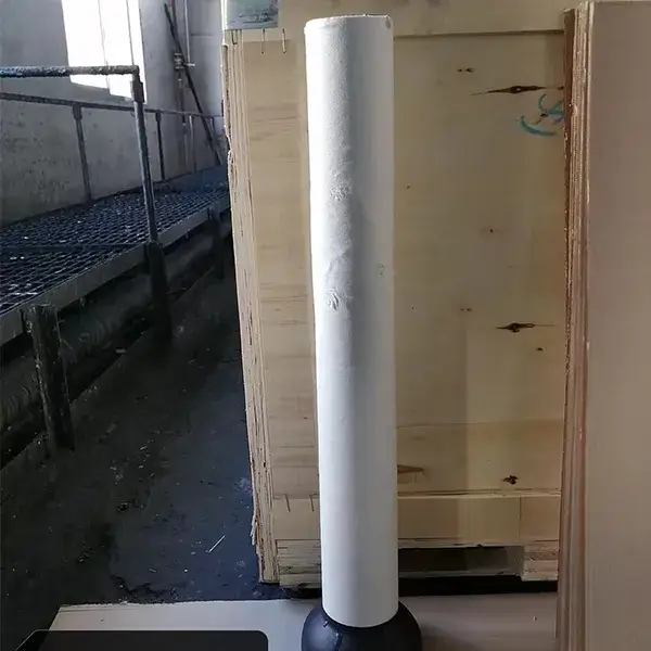
Therefore, today, graphite and alumina are used as raw materials, phenolic resin is used as binder, and antioxidants are added. After mixing, isostatic pressing (CIP) molding and firing, and mechanical processing is used to make long nozzle bricks, integral stopper rods and submerged nozzle bricks.
This molding (CIP) method achieves the requirements of uniform internal structure and stable quality for large integral products.
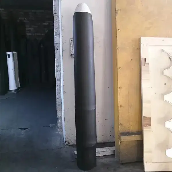
For submerged nozzle bricks, the lower part (the part in contact with the mold slag during actual operation) is generally covered with zirconium graphite (ZG) refractory material with good resistance to mold slag.
The development of continuous casting refractory products has led to the introduction of isostatic pressing (CIP) molding process into the manufacture of refractory materials.
(1) The length/diameter ratio of the long nozzle brick, the submerged nozzle brick and the integral stopper is too large to be pressed by an ordinary double-sided hydraulic press. Only by using isostatic pressing (CIP) can the pressure on the pressing surface be uniform, and the volume density of the cross-section of each part of the brick blank be uniform.
(2) Isostatic pressing (CIP) can press high-graphite content corundum-graphite mud materials with low binder content and poor plasticity that are difficult to press.
(3) Since the long nozzle brick, the submerged nozzle brick and the integral stopper are made of high-graphite content corundum-graphite materials, only isostatic pressing (CIP) can avoid the occurrence of cracking in the brick blank and ensure the quality of the brick blank.
The above-mentioned high-graphite content corundum-graphite mud materials are mainly formed by wet bag isostatic pressing of long nozzle bricks, submerged nozzle bricks and integral stopper.
The entire forming process of long nozzle bricks, immersed nozzle bricks and integral stopper rods is divided into:
(1) Mold filling. Powder is placed in a rubber mold. When forming large parts, the mold is placed in a support box.
(2) Mold sealing. The assembled mold is sealed with a sealing plug. In some cases, it is necessary to evacuate the mold to remove some of the gas before sealing.
(3) Place in a high-pressure container. Place the sealed mold together with the support box into a high-pressure container, and then fill the high-pressure container with liquid.
(4) Pressurization. After the high-pressure container is covered, the liquid and the mold are simultaneously subjected to pressure. The powder is compressed from all directions to form a dense green body.
(5) Mold removal. After the pressure of the liquid in the pressure container is removed, the air escapes from the pores of the green body and surrounds the green body. The rubber mold returns to its original shape. After removing the support box, the green body can be removed.